ABS WHEEL SPEED SENSOR TESTING
How To Test ABS Wheel Speed Sensor
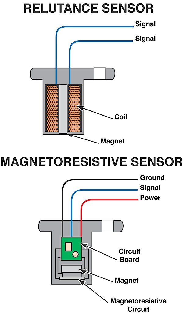
Use your trusty multimeter to check continuity through wheel speed sensors.
This sensor has a value of about 1.5 K ohms.
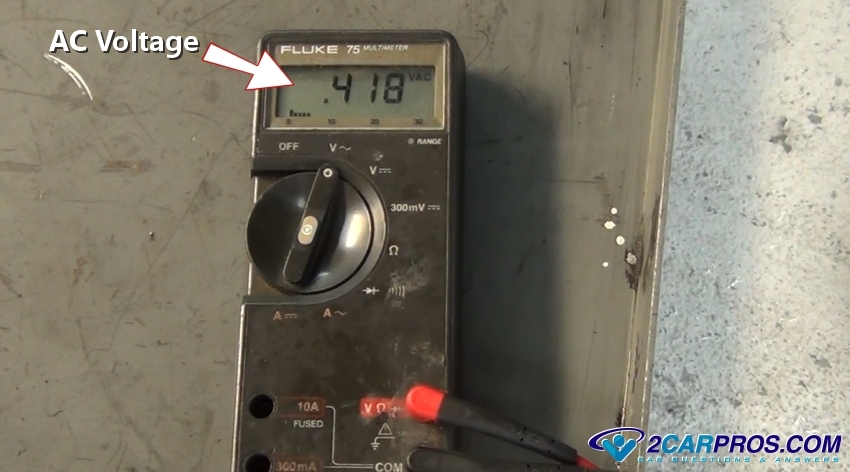
AC VOLTAGE
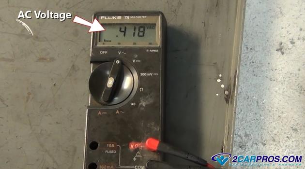
With the meter set to AC voltage, spin the wheel by hand. The sensor should produce between .5 to 1 volt of AC current. The faster the wheel is spun, the more voltage is produced.
BIAS VOLTAGE PASSIVE
SENSORS
Some vehicles will send a DC voltage to the sensor through the ground wire. The signal will ride up on the DC signal. This is done so that the sensor can be tested by the ABS system without the vehicle moving. These types of vehicles will set WSS codes the moment the key is turned on. You can clear a WSS code and the moment the key is turned on, the code will immediately be back.
The ABS computer is looking at the voltage coming back from the sensor. High resistance or an open circuit can be immediately detected. Often, with these systems the trouble is not the sensor, but the bias voltage as it goes through the harness and connectors.
If the signal is viewed on a scope, the voltage will raise above the ground or zero line. On this vehicle, there is a 2.5-volt bias. To measure this, have the ground lead on the battery ground, and the positive lead connected to the signal wire. Without the wheel spinning, you can observe the DC voltage being supplied to the circuit.
With the sensor disconnected, connect the positive lead to the signal wire and the negative lead to the other side that is the ground for the ABS module. This voltage comes directly from the ABS module and will be between 1.5 and 5 volts. This is the bias voltage from the ABS module. Any voltage outside of the manufacturer’s specification may indicate a problem with the harness.
UNWANTED ABS ACTIVATION IN PASSIVE WSS
You never want to underestimate a little bit of rust under a WSS. A little bit of rust between the WSS and the knuckle or hub can disturb the air gap between the WSS and the tone ring.
You want to clear the rust and polish the surface. Never grind the surface. This could cause further problems. If removing the corrosion does not resolve the problem, you should look at the tone wheel. Tone rings or wheels are mounted on axles, CV joints and hubs. The majority of tone wheels are pressed on to these components.
Other electrical outputs can cause interference in the WSS wires. Wires for the ignition system, charging and serial data buses can cause interference that can lead to false activation. Some OEMs have even issued TSBs directing technicians to reroute or even shield affected wires.
ACTIVE WHEEL SPEED SENSORS
Active WSS use two wires and look like passive wheel speed sensors. Active WSS are used on most newer vehicles because they are more accurate at lower speeds and can detect 0 mph. Also, active sensors can even detect if the vehicle is moving in reverse.
Active WSSs output a digital signal. The signal is a Direct Current (DC) square wave signal. The signals are different than a camshaft or crankshaft position sensor.
The end of an active WSS is typically a flat blade tip that is mounted next to a tone ring. The sensor’s tip is typically buried inside a hub or knuckle.
TESTING
Like passive WSSs, it is possible to look at the data from the WSS using a scan tool. A scan tool can be used ri graph the WSSs. You should look for a clean signal from each sensor. All signals should track the same. When the vehicle is stopped, they should all evenly drop.
Active wheel speed sensors have two wires. One wire provides 12 volts to power the sensor. The other wire is the signal wire. The signal wire changes the frequency of the waves as the magnets of the tone ring pass by. This makes for a very accurate sensor at low speeds.
TELLING THE DIFFERENCE
If you disconnect the sensor and probe the harness with the ground lead connected to the battery ground and the positive lead into the harness, you will see a voltage of 11.30 with the engine off.
If you probe the signal wire,
you will see a voltage of .03
volts. You might confuse this reading with a bias voltage passive sensor, but the values are significantly different.
When the vehicle is started, the power supply changes from 11.30 volts to 13.69 volts, which is the charging system voltage. But, the signal wire remains at .03 volts. When the sensor is plugged into the harness, the voltage drops to 12.07 volts with current running through the sensor. This voltage does not change if the vehicle is moving; it is just a power supply.
With the black lead on the battery ground and the red lead back probed into the signal line, the wave pattern generated by the sensor can be observed.
What is unusual is the voltage levels of the square wave pattern. The wave goes from between .6 to 1.2 volts. The square wave is only .6 volts high and never connects to ground or zero. Also, it never shows the battery voltage. This is a very small square wave out of an active sensor.
If you were to back probe the connected sensor with the positive lead connected to the signal wire and the negative lead to the other wire connected to the sensor’s power supply, you would still see a square waveform. This waveform would toggle between 12 and 12.7 volts. This is still a .6-volt square wave like is seen above.
RESISTANCE TESTING
ACTIVE WSS CANNOT BE TESTED BY USING THE RESISTANCE ACROSS THE SENSOR.
If you do measure an active sensor with a meter, it will produce a reading around 3.5 millions ohms. If the leads are reversed, you will get an infinite reading indicating an open circuit. The second reading would indicate a dead passive WSS or a normal active WSS. This makes the results dubious.
On the harness side, it is possible to determine if the sensor is passive, passive with a bias voltage or active. Passive systems have no voltage. Bias voltage systems have between 1.5 to 5 volts. Active systems have between 12 and 12.7 volts.
AMP METER TESTING
An amp meter can be used to check active wheel speed circuits. The amp meter must be installed in series in the signal line. Setting this up in reality can be tricky with jumper wires. And the voltage test above might be quicker. The amp meter should read between 7 and 14 milliamps.
CURVEBALL: HONDA, ACURA AND BMW
On some newer vehicles, when the sensor is unplugged, the power or bias is turned off. If the sensor was plugged in and the key was cycled, it would appear again. In these cases, back probing the sensor would be the best way to test the sensor.
Over the river and through the woods was more dangerous back when cars had crummy bias-ply tires, rear-wheel drive and ordinary brakes. So, tonight you feel confident driving home through several inches of freshly fallen snow after a sumptuous holiday dinner. Your front-drive car has excellent all-season tires and ABS (antilock braking system)—although the ABS light has been on since you banzai'd the berm at the end of the driveway an hour ago. This may explain the loss of steering control when you're slowing down for a corner. Like this downhill turn, right ... there, as you blow straight past it with the wheels skidding and the steering cranked over hard against the stop.
ABS has become pretty much standard equipment on most vehicles. Sensors tell a computer when a wheel stops rotating, which indicates—at least when the vehicle still has forward speed—that the brakes have overpowered the available traction at that particular wheel. The computer then directs a hydraulic valve to release some brake fluid pressure to the wheel to let it rotate again. This process repeats many times per second until the vehicle stops or you lift your foot off the brake pedal. The ABS computer does a power-on self test every time you cycle the ignition. If it finds it's lacking data, or a hydraulic pump or valve isn't responding, it illuminates the ABS warning light on the dash. ABS relies on a properly operating conventional brake system. If the ABS packs up, you should still have normal, unassisted braking, so it's safe to continue your journey.
An ABS wheel speed sensor (WSS) is used to send feedback information (voltage) back to the system computer module to help determine at what speed the tire is turning at, furthermore the computer looks for and monitors all four wheels to unsure consistency between them.
Once the computer detects one of these wheels is rotating slower compared to the others the computer signals the appropriate fluid control valve to dump brake pressure which allows the wheel to roll again and regain traction.
When one of the sensors fails due to usage or damage the system will trigger an ABS warning light. In this video and repair guide we will show you how to test these sensors.
Please watch the video below and then continue onto the guide to pick up additional tips and information.
Testing these sensors is not difficult and it will take some basic tools and a voltmeter but it will save you money and takes less then an hour. Lets get started!

When the initial loosening takes place, always push down on the lug wrench this will aid in the leverage needed without hurting your back. Continue to loosen the lug nuts one or two full turns (Do not fully remove the lugs at this time, that will be done in later steps).

If you can get to the sensor connector with out removing the wheel then you can skip this step, we removed the wheel to aid in this demonstration.

If the sensor has failed replacement is necessary, configuration of the sensor mounting is different from manufacturer to manufacturer but follow the same operation so check your before replacement begins. Learn more
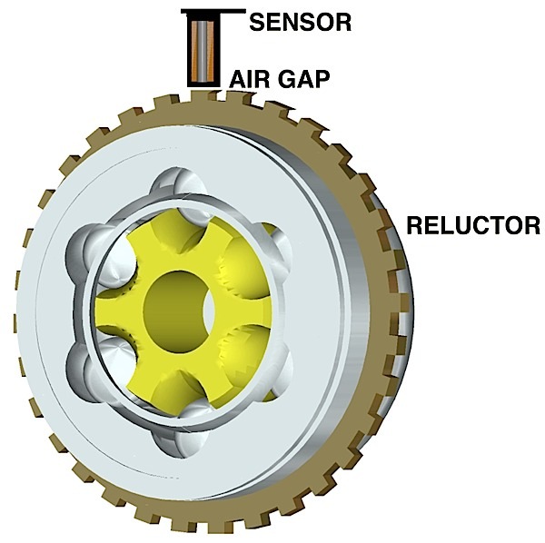
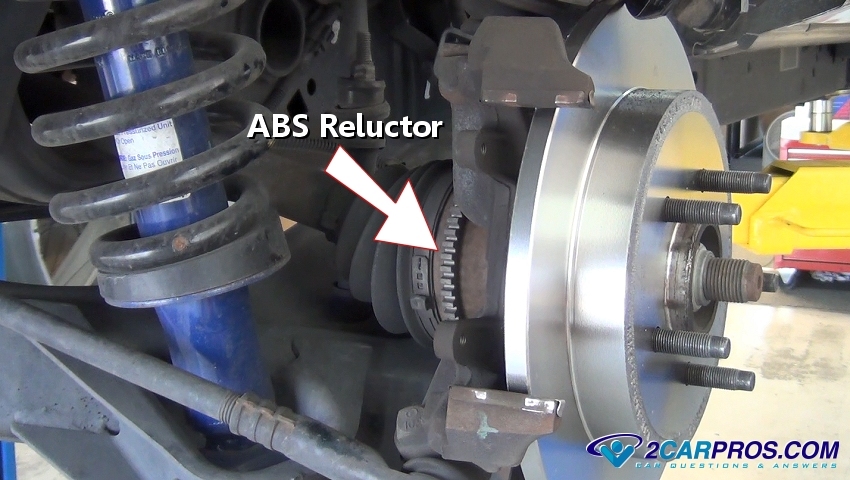
Below is a system stator which is used by the sensor to determine the speed of rotation and can be located either inside the bearing hub or axle housing on the rear of the vehicle, or just outside on the CV axle itself. A stator wheel is what actually rotates with the wheel and is used in connection with the sensor, if this wheel is damaged or missing the warning light will be on while disabling the system from operation.

Once the computer detects one of these wheels is rotating slower compared to the others the computer signals the appropriate fluid control valve to dump brake pressure which allows the wheel to roll again and regain traction.
When one of the sensors fails due to usage or damage the system will trigger an ABS warning light. In this video and repair guide we will show you how to test these sensors.
Please watch the video below and then continue onto the guide to pick up additional tips and information.
Testing these sensors is not difficult and it will take some basic tools and a voltmeter but it will save you money and takes less then an hour. Lets get started!
STEP 1
Using the opposite side of a lug wrench or a large standard screw driver gently remove the hubcap by slowly working around the tire until the hubcap is free from the rim. If your car is not equipped with a hubcap, (many cars a don't use a hubcap) omit this step and continue onto the next step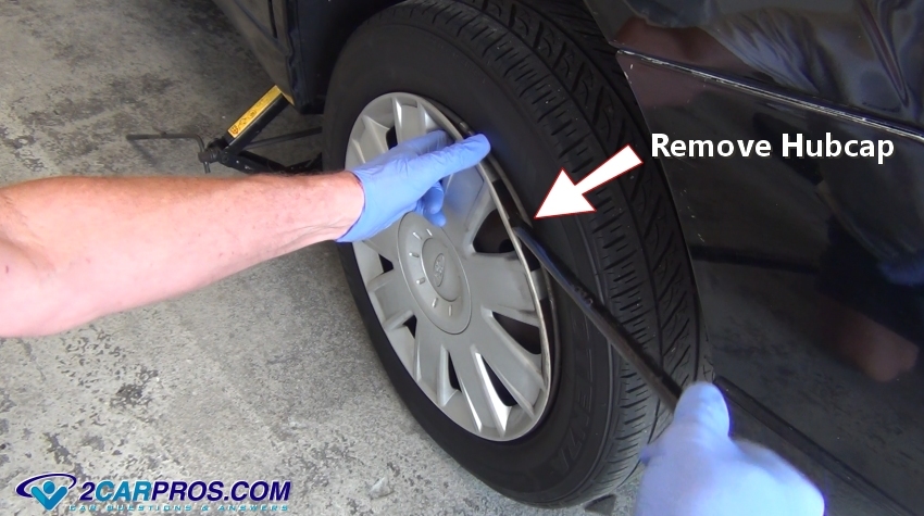
STEP 2
The next step is to break the lug nuts loose by turning them counterclockwise before jacking up and lifting the car, this will help you loosen the lug nuts without the tire rotating on you. Lug nuts can be very tight so make sure the lug wrench is fully on the lug nut to avoid stripping or rounding. It can help loosen the lugs nuts by applying a lubricate such as wd40 to aid in their removal if needed.When the initial loosening takes place, always push down on the lug wrench this will aid in the leverage needed without hurting your back. Continue to loosen the lug nuts one or two full turns (Do not fully remove the lugs at this time, that will be done in later steps).
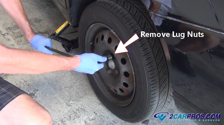
STEP 3
Next, safely lift your car off of the ground using a hydraulic jack and securing the vehicle using jack stands for safety. Once the car is safely lifted continue to remove the lug nuts and then remove the tire, once the tire is off the car, truck, or SUV slide it under the vehicle for additional safety.If you can get to the sensor connector with out removing the wheel then you can skip this step, we removed the wheel to aid in this demonstration.
STEP 4
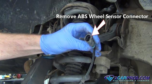
After the tire has been removed locate the wiring from the sensor that connects to the sensor. Don't be confused by other wiring that may lead down to the wheel such as the brake pad wear sensor. Once located disconnect the sensor at the connector by releasing the safety clasp and gently pulling it apart.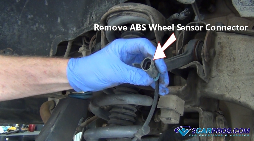
STEP 5
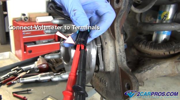
The previous step will uncover the sensor electrical terminals which is what you will be using for testing proposes, the voltmeter probes will be attached to these terminals.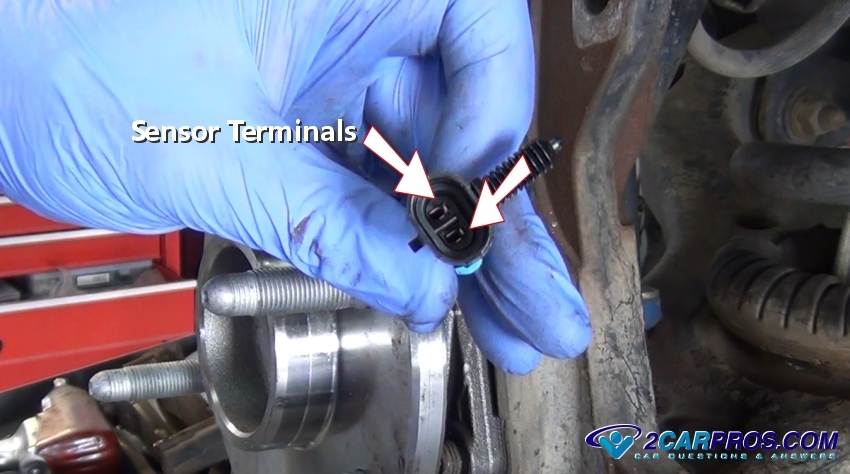
STEP 6
Using the voltmeter alligator clips, attach the voltmeter leads to the sensor, be sure to not allow these test probes to touch internally or the sensor will not test properly. Try not to use hand held probes because they can wiggle causing the voltmeter readings to fluctuate which makes testing more difficult and can offset the test.
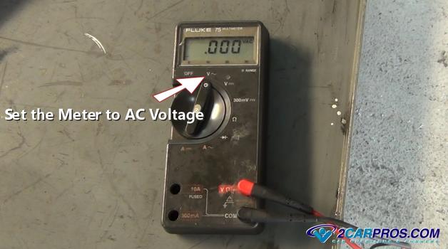
STEP 7
Once the leads have been connected using the clips, set the meter to AC (alternating current) voltage. AC voltage is what is generated by the sensor and stator ring as the positive and negative magnetic fields are built up and then broken down while the wheel spins. The meter will usually indicate AC voltage by a wave symbol. Once the meter is turned on it will fluctuate down to zero volts, now the sensor is ready to be tested.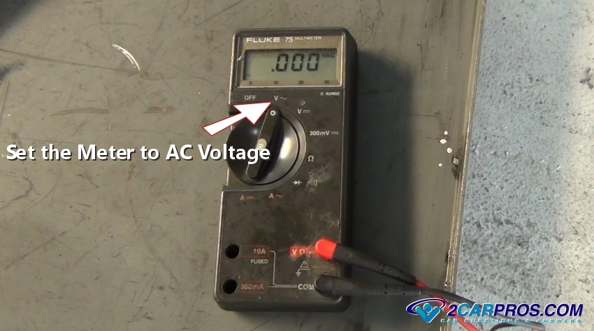
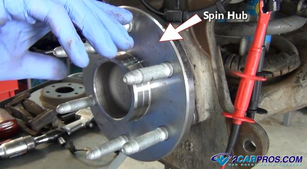
STEP 8
While observing the voltmeter simply spin the wheel or hub to create voltage, this voltage will vary according to the speed in which the hub or wheel is spun. As the hub begins to spin the voltage will rise and then decrease as it stops.
STEP 9
While the hub or tire is rotating the sensor should produce voltage which will follow the speed of rotation. If no voltage is observed the sensor has failed or on rare occasion the air gap is too excessive due to a failed axle bearing, also check the stator wheel for damage/missing teeth.If the sensor has failed replacement is necessary, configuration of the sensor mounting is different from manufacturer to manufacturer but follow the same operation so check your before replacement begins. Learn more
Below is a system stator which is used by the sensor to determine the speed of rotation and can be located either inside the bearing hub or axle housing on the rear of the vehicle, or just outside on the CV axle itself. A stator wheel is what actually rotates with the wheel and is used in connection with the sensor, if this wheel is damaged or missing the warning light will be on while disabling the system from operation.
Item To Be Tested
Ignition Mode
Measure Between Pins
Tester Scale/Range
Specification
Pinpoint Test
Power Feed
Battery Check
off
batt. Terminals
volts
10 minimum
Ignition Mode
Measure Between Pins
Tester Scale/Range
Specification
Pinpoint Test
Power Feed
Battery Check
off
batt. Terminals
volts
10 minimum
ABS ECU Power
on
14 + 1
volts
10 minimum
DTC B 1318
Pump Motor Power
off
2 + 1
volts
10 minimum
DTC C 1095
Valve Power
off
13 + 1
volts
10 minimum
DTC C 1266
Sensor Resistance
LF Sensor Resistance
off
15 + 16
K ohms
1.28-1.92 K ohms
A
RF Sensor Resistance
off
20 + 7
K ohms
1.28-1.92 K ohms
B
LR Sensor Resistance
off
17 + 18
K ohms
1.28-1.92 K ohms
C
RR Sensor Resistance
off
4 + 19
K ohms
1.28-1.92 K ohms
D
Sensor Continuity to Ground
LF to Ground
off
15 + 1
continuity
no continuity
A
RF to Ground
off
20 + 1
continuity
no continuity
B
LR to Ground
off
17 + 1
continuity
no continuity
C
RR to Ground
off
4 + 1
continuity
no continuity
D
Sensor Output Voltage
Rotate Wheels at One Revolution Per Second
LF Sensor Output
off
15 + 16
AC mV
> 100 mV
A
RF Sensor Output
off
20 + 7
AC mV
> 100 mV
B
LR Sensor Output
off
17 + 18
AC mV
> 100 mV
C
RR Sensor Output
off
4 + 19
AC mV
> 100 mV
D
ABS Warning Lamp Check
on
22 + 1
volts
10V minimum
E
Stoplamp Switch Check
Brake Pedal Applied
off
9 + 1
volts
10 minimum
Brake Pedal Released
off
9 + 1
continuity
no continuity
If you need more information about this article please visit our forum which has hundreds of previously answered questions about ABS wheel sensors have been answered by our mechanics.off
9 + 1
continuity
no continuity
wheel speed sensor (WSS) fails or there's a problem in the sensor's wiring circuit, it usually disables the ABS system and causes the ABS warning light to come on. Loss of a wheel speed signal is a serious problem because the ABS module needs accurate input from all its sensors to determine whether or not a wheel is locking up. Without this vital information, the ABS system can't do its thing.
ReplyDeleteStart once you have determined you are going to fix the problem, park the car on level ground with the transmission in park and the emergency brake set and the engine turned off.
1. LOCATE AND REMOVE THE CONNECTOR
2. VOLTMETER SET UP
3. PERFORM TEST
Source : http://techprotools.blogspot.com/
https://aircooledcommunity.com/blog/abs-light/
ReplyDeleteYou should see how my associate Wesley Virgin's adventure begins in this SHOCKING and controversial VIDEO.
ReplyDeleteAs a matter of fact, Wesley was in the military-and soon after leaving-he found hidden, "SELF MIND CONTROL" secrets that the CIA and others used to get anything they want.
THESE are the EXACT same SECRETS tons of celebrities (especially those who "became famous out of nowhere") and elite business people used to become wealthy and famous.
You probably know how you use only 10% of your brain.
That's really because most of your brainpower is UNCONSCIOUS.
Perhaps that thought has even taken place INSIDE your own head... as it did in my good friend Wesley Virgin's head seven years ago, while driving a non-registered, trash bucket of a vehicle with a suspended driver's license and with $3 on his debit card.
"I'm so fed up with going through life paycheck to paycheck! When will I finally make it?"
You took part in those types of thoughts, am I right?
Your success story is waiting to start. All you need is to believe in YOURSELF.
CLICK HERE To Find Out How To Become A MILLIONAIRE